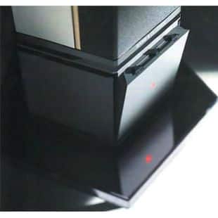
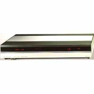
BeoCord 7000
BeoCord 7000
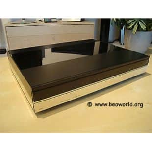
Beocord 7000 was a high-quality cassette recorder used specifically with Beosystem 7000. When playing cassettes, the order of the tracks could also be changed and the recorder could also find a specific track on a tape. Other functions included Auto Reverse, Auto Record levels, Dolby B and C as well as Bang & Olufsen’s recording system HX-Pro, which ensured that the sensitive treble range is captured in recording.
Beocord 7000’s features were supplemented by an abundance of special features. Space available precludes a more full description of elements such as the design of the peak programme meter, locally operated functions such as microphone recording, memo set/go, adjustment of the maximum record level and so on.
Main features:
* Auto record level
* Auto track search/auto reverse
* HX Pro
* Auto Dolby B-C
* Auto tape switch
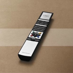
* All operation available from Beolink 7000, with full display readout of track bar, counter, record level, Dolby NR, auto reverse functions, sequence programming etc.
Recording with Beosystem 7000 was a system feature, with benefits such as automatic signal routing, record lock, etc. Beocord 7000 contributed a lot to the convenience of the system and the unique auto record level was the feature that made remote controlled recording a real possibility – without compromising the quality of the recording. To further ensure a high and consistent sound quality level Beocord 7000 was equipped with HX Pro.
Auto record level
Auto record level is a unique Bang & Olufsen feature and ensures a uniform and optimal recording level from all sources, from tape to tape, without overload. Major benefits of auto record level are:
* all tapes recorded with auto record level have the same optimum level, without overload and therefore without distortion
* a recording can be started immediately and directly, without any pre-adjustments
* you do not have to supervise a recording to adjust record level and the system recording even stops the recording when the source runs out, or stops the source when the tape runs out
* if auto record level interferes and adjusts the recording it is done in such a way that it is not noticeable in playback. The dynamic range of the recording will not be impaired and the adjustments are carried out so early that overload is precluded.
The assets of auto record level are obvious when a comparison is made between those carried out on a standard recorder without auto record level and those with.
Recording on a standard recorder requires you to supervise the recording in order to step in if the manually set input level is too high. In this case you would have to adjust the record level down when a signal with a high dynamic content is to be recorded. If this is not carried out the tape will be overloaded and the music distorted. Without auto record level, copying is in real-time, which means that you will have to pay attention all the time you are recording (or risk a distorted recording). And when a very wide dynamic signal threatens to overload the tape being recorded, the record level must be lowered quickly, which will often be audible in subsequent playback, either as a suddenly lowered output volume or as a distorted signal because the record level was lowered too late.
Auto record level is an efficient remedy to this problem, without both disadvantages mentioned above. Primitive solutions reduce the record level when powerful signals are recorded and increase the record level when weak or no signals are recorded. The result can be a fluctuating dynamic range with, for example, pauses between tracks causing the recording level to rise dramatically and the noise level with it.
The Bang & Olufsen solution
The auto record level in Beocord 7000 was monitored by the microcomputer interacting with the peak programme meter indicator on the front of the cassette deck. Auto Record Level only reduces the record level and only if the signals exceed the set value for a certain period. In this way brief noise pulses, such as the ones resulting from scratches on a record, do not lower the record level. When a signal of more than +2 dB above the set value is encountered, the microcomputer lowers the record level with 2 dB. The recording continues at the lowered level unless even louder signals appear and trigger new reductions.
Other advantages of auto record level are:
* it is applied to all sources, even if you record sound from a video source
* the preset values can be changed, e.g. if you use special tape formulas
* auto record level can be overridden while you are recording, or you can make a recording with manual adjustment of the record level
You did not have to pre-adjust Beocord 7000 before you started a recording. Another feature was the auto tape switch, i.e. an automatic adjustment to the three tape types, metal, chrome and ferro, by means of three electronic sensors located in the cassette holder. Auto-reverse was the default mode both in recording and playback, i.e. Beocord 7000 automatically continued the recording (and playback) on side two, when side one ran out. The turning time from side one to two was very short, because an optic sensor registered the lead-in tape and executed the 180 degree turning of the tape head immediately. Auto reverse could be cut out manually to protect side two from being recorded. This had to be done prior to record start.
Track Search
Beocord 7000 featured track search, based on pauses between individual tracks. You could also make a sequence programming, operated just like CD. Track search was available no matter if the track was on side one or two of the tape. Even if you executed a manual TURN function (i.e. change playback direction) the microcomputer registered the turning point and if you selected a track after the turning point the search for this track would be initiated at the turning point. Track numbers could be displayed on Beolink 7000.
Auto Dolby
Another convenience was the Auto Dolby function. All tapes recorded on a Beocord 7000 contained inaudible information as to whether the tape was recorded with Dolby B, Dolby C or no Dolby noise reduction. The registration of noise reduction type was dynamic and in case the circuit registered a change during playback the reduction was automatically changed. If no signal was registered, e.g. on a pre-recorded tape, the noise reduction last selected would remain active, until altered manually (see more below).
HX-Pro
Beocord 7000 was equipped with HX Pro, like all other ‘stackable’ Bang & Olufsen audio tape recorders. HX Pro is an acronym for Headroom Extension Professional and tapes recorded with HX Pro give a better reproduction quality on playback, no matter which tape deck they are played on. Both the dynamics and the the signal capability in the treble range is improved. The improvements are most noticeable in the reproduction of treble signals, but also the midrange will be influenced in a positive way. At 10KHz the signal loading capability is improved by approximately 8dB for chrome tape, 5dB for ferro tape and 3dB for metal tape formulas.
Beocord 7000 could ideally be used as part of Beosystem 7000.
BeoCord 7000 Product Details
Type Numbers
4941 (1992 – Dec 1995)
4945 (AUS) (1992 – July 1995)
4942 (GB) (1992 – Dec 1995)
4944 (J) (1992 – Dec 1995)
4943 (USA) (1992 – Aug 1996)
Designer
Manufactured
1992 – 1995
Colour Options
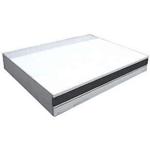
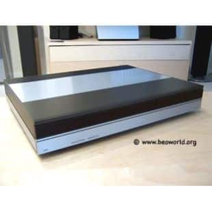
Aluminium, Black, White
BeoCord 7000 Product Specification
Recording system HX PRO
Tape transport Auto reverse
Noise reduction Auto Dolby B-C NR
Frequency range chrome 30 – 18,000 Hz
Signal-to-nose ratio chrome Dolby B > 65 dB
Power supply:
4941 220V
4942 240V
4943 110V
4944 100V
4945 240V
Power consumption/minimum max. 19 W / 6 W
Dimensions W x H x D/Weight 42 x 7.5 x 32.5 cm / 8.35 kg
Cabinet finish: aluminium, white, black
Connections: Microphone DIN
Gold or Silver membership required to view documents
Available documents are listed, if none are listed then please reach out to see if we have them.
BeoCord 7000 FAQs
Please let us know


