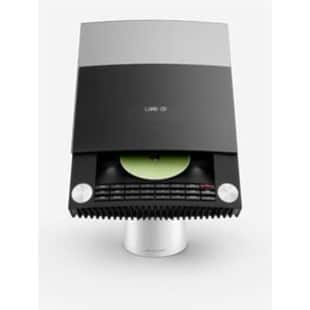
Q: Are these HDTVs?
A: No. They are, however, very high-quality standard-definition CRT TVs with a resolution of 480i (interlaced) lines of resolution. They were designed with a primary input source, the S-VHS VX5000 VCR, which came very close to today’s DVD resolution. Under ideal conditions, a S-VHS tape might contain 400 lines of resolution, versus a DVD’s 480 lines. So it’s safe to say they were engineered with very high-quality signals in mind.
Q: What inputs do these sets have?
A: The highest-quality input generally available is the single S-Video plug on the back. The VCR1 Scart connector contains RGB inputs, although these are mainly used for sending the menu overlays from the VX5000, rather than the video signal itself. The RGB input standard can be usefully compared to Component (YPbPr) input in terms of quality. Theoretically, a DVD player outputting NTSC signal over Scart, such as the DVD1, might be able to send a RGB signal over the VCR1 input. Reports from the field are welcome.
Q: How much do these sets weigh?
A: 114lbs. So be very careful moving one.
Q: What is the difference between the MX5000 and the MX5500?
A: Very little. The tubes were from different manufacturers (RCA versus Toshiba?). MX5000s have one-way Infrared software, MX5500s have two-way software. Both have the two-way IR hardware installed. MX5500s are newer.
Q: Where is the two-way Infrared hardware located on the set?
A: At the top right corner, in the same area as the red standby LED.
Q: If the MX5000 has two-way Infrared hardware, can I upgrade the software to use it?
A: Yes, just order version 2.2 of the software for about US$50 and install it. Don’t open the back of a TV set unless you know what you are doing, however.
Q: What two-way remotes work with an MX5500 (or upgraded MX5000)?
A: BeoLink 5000 and BeoLink 7000.
Q: Why do I see a small white bar on the screen when I change the volume?
A: This is the set’s strange way of letting you know it has received a command over Infrared.
Q: What software versions are available for these TVs?
[code]
1.6
1.8
1.9 Bug fix for AM/PM in clock
2.2 Two-way Infrared. Part #8341369
2.2S For use with AV7000, disables Infrared altogether. Part #8342505[/code]
Q: Can I use the MX5000 and MX5500 with an AV7000?
A: Yes, with some limitations. You’ll need a special software version, 2.2S (see above.) This will totally disable the internal Infrared, so you’ll lose two-way communications. Also, the internal speakers must be disconnected. Finally, the AV7000 software revision that controls DVD players removes support for the MX5000 and MX5500.
Q: My external PowerLink speakers make a noise when I change the channel.
A fix was introduced in April 1990 to eliminate a brief ‘pop’ of static from attached PowerLink speakers when changing channels on the built-in antenna/cable TV tuner. This is a very small circuit board which must be soldered to two points on two separate boards. Atlantic Systems will generally perform this fix when they rebuild a board. Here is the wiring diagram:
Q: The speakers sound bad. Are they worn out?
A: The foam-rubber surrounds may suffer from ‘foam rot.’ New drivers are available for a total cost of US$50 for both and are relatively easy to install. The drivers have push-on terminals and do not need to be de-soldered:
Q: OK, but how do I remove the cloth grille covering the speakers?
A: Very carefully. You’ll need to run your fingers over the grille on the left side of the set as you stand in front of it (the set’s right side). You’ll feel two rectangular holes. Gently push a blunt instrument into them to release the two plastic clips. Take care not to tear or stretch the fabric. Once the left side is released, it should pop out about an inch.
Use the leverage to gently pull the grille off the front of the set. It may help to pinch the top and bottom together to create enough space to release the other clips. The right side does not need to be released in the same way as the left; it should come free once the front is released.
Or, you can follow the service guide’s official instructions:
[quote]Carefully insert a screwdriver between the loudspeaker panel and the cabinct in the right-hand side of the set.
Loosen the loudspeaker panel by exerting a light pressure with the screwdriver.
Push the loudspeaker panel towards the left.
A light push against the left corner of the loudspeaker panel will now release the panel completely.[/quote]
Q: Can I get a new front grille replacement?
A: Yes, for about US$50. It will be a slightly different plastic frame, but you won’t notice this once it’s installed. The original is at the bottom, the new replacement is on top:
Q: I want to change the color of the case.
A: White, Red and Blue cases are still available as a spare parts for about US$90. Black is all gone. The colored back case is separate from the black, non-painted plastic center unit in the back. The painted shell is what you replace, keeping the center.
Q: Can I buy a MX6000, MX7000 or MX8000 back case from Europe?
A: No, the mounting points on the center are very slightly different.
Q: I am repairing an NTSC MX5000 or 5500. Are there any resources online to help?
A: Jean Vezina has written a repair guide covering the replacement of aging capacitors in these TV sets. It is available on the Connoisseurs’ Club <a href=”http://www.beoworld.co.uk/connoisseursclub/servicemanuals/mx5000repair.zip”>here</a>. Remember TV sets can contain fatal voltages; always refer servicing to an trained specialist if you are not experienced with high-voltage CRTs.
The official B&O Service Guide for this set is also available. Untill the BeoWorld site redesign, contact moderator PL212 for access.
Q: How can I access the service counters in the MX5000 and MX5500?
A: In the TV Menu, set the time and date to:
Time: [color=red]33:30 am[/color]
Date: [color=red]Mar 16 3250 Thu[/color]
Press PLAY on the remote.
[code]A x 10 = Picture tube ON time.
B x 10 = Audio only ON time.
C x 10 = Stand by time.
D = Only used in production.[/code]
Q: Is there any built-in test pattern in these sets?
A: A very simple one. Activate the service counters, as shown above. Then press 2 and an On-Screen Display color adjustment picture appears. Press TV to go back to normal TV mode.
Q: Can I use a North American DVD1 on these sets?
A: Yes. (Details to come.)
Q: Can I use a North American BeoCenter 2 on these sets?
A: Yes, in theory. Connect a 21-pin, fully-wired SCART cable between the SCART on the Socket Unit to AV1 (B&O VCR) on the MX. Configure the SCART on the TV as VTAPE. You will also need a BeoLink Converter to adapt the BC2’s MasterLink to the MX’s MasterControlLink. (If you don’t have a BeoLink Converter, you will need to mute the TV’s sound and then select CD on the remote. You will have control of the Beocenter 2 and use of the speakers connected to the BC2.)
Unresolved questions:
Will the BeoCenter 2 work with a SCART break-out cable attached to AV2? If so, will it work as VTAPE2 or CDV?
Are PowerLink speakers best connected to the MX or the BC2?
Thanks to Linder for information about the BC2.
Q: What is the DECODER (EIA IS-15) port on the back of the set?
A: [color=blue]Electronic Industries Association Interim Standard 15[/color]:
The Television Receiver Committee of the EIA proposed a baseband interface standard, IS-15 for improving the compatibility between TV receivers and cable TV (CATV) decoder systems. The advantage of using this standard is the ability to integrate tuning, intermediate frequency, and remote control systems for both TV and CATV applications. As a result, the RF converter can be eliminated and descrambling can be achieved in the baseband.
It’s a stillborn attempt at a North American standard for controlling cable/satelite boxes, based on the successful European SCART/Peritel system. Invented by E. Lykkegaard and K. R. Jensen of Bang & Olufsen, the hope was that cable boxes and other external decoders could be controlled by the TV set itself, changing the channels as necessary for timer recordings, etc. Nothing ever supported it.
Relevant links:
http://ieeexplore.ieee.org/xpl/freeabs_all.jsp?arnumber=20186
Q: So can I use the EIA IS-15 port for anything then?
A: Good question. We have the information on the pinouts of the connector and what each signal does. (Information to be posted soon.) It’s not just a simple video-in port, however — it has complicated bi-directional communications that might have to be emulated by an external device.
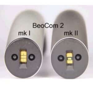 You can tell at a glance the difference between the Mk1 and Mk2 versions by simply looking at the actual and of the phone that sits in the charging base.
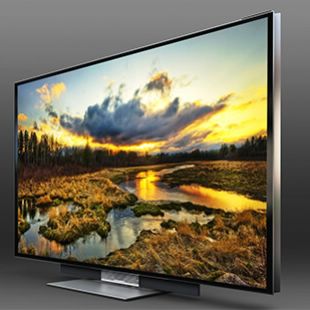
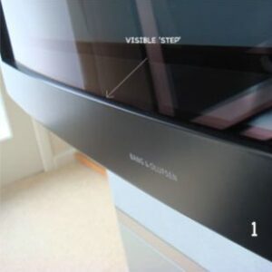 Many people when referring to their BeoVision Avant are asked by Dealers, Service Engineers or potential buyers “Is it a Curved or a Real Flat?”
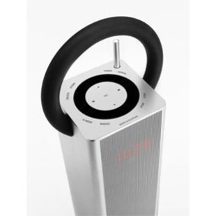
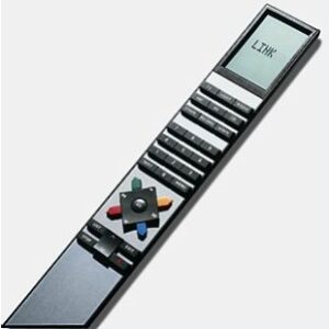 The first remote control product made by B&O was the Beomaster 6000 quadraphonic receiver. This used an ultrasonic remote control that operated only the receiver.
 If you source unit (Tape recorder, Beogram or CD player) is attached and has datalink and the Beomaster also is Datalink enabled, the first thing to do is check the cable. B&O utilise the DIN standard of connectors and for Datalink, this means a 7 pin DIN cable. The bottom two pins (6&7) carry the Datalink transmissions.
 Worrying about the distorted picture ( a black bar on the right side ; lowest part of picture appears on the upper top )?
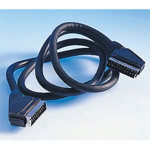
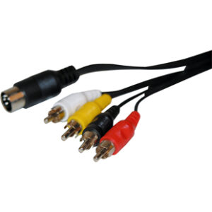 There are various adapters that you can buy. Most home audio products (and non-B&O TVs) have RCA (also called phono or cinch) sockets fitted, you you just need a twin RCA to DIN cable connected from the Line Out or Tape Out sockets of the non-B&O product to the Aux or Tape socket of the B&O system for playback of sound into the B&O system.
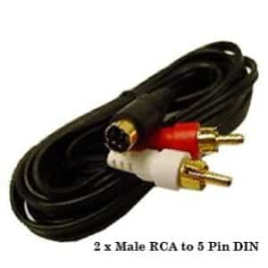 The majority of Bang & Olufsen systems have circular ‘DIN’ connections on the rear/connection side of the unit. You can use a ‘Mini-Jack’ (the kind of plug you find on the end of iPod headphones) to a ‘DIN’ cable (see image).
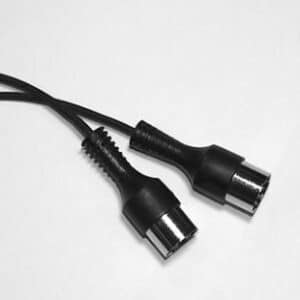 For those speakers with a display, you need a fully wired Powerlink cable. Speakers needing this type include the Pentalabs, Beolab 3000, and Beolab 5000. These are commonly known as ‘Mk2’ and are much thicker than Mk1 or Mk3.