Beomaster 6000 History
Beomaster 6000 was the realisation of the Topline prototype on which work had progressed over the preceding years. The long flat cabinet of the Beomaster 1200 with its operation from the top and the depressed knobs was repeated. But the Beomaster 6000 is the first representative of a new phase in Jacob Jensen’s oeuvre. The slide rule motif symbolised mechanical precision, but now the entire idiom is adapted to the abstraction it was necessary to submit in communicating using electronics.
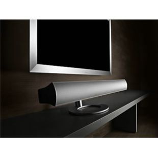
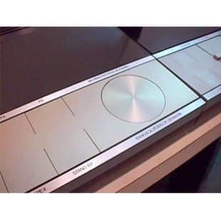
The visually, symbolically and tactilely easily understood slide rule operation belonged to the age of mechanisation and must be understood in extension of the modernistic machine aesthetics of the 1920s. The design of the Beomaster 6000 emphasises that it belongs to the electronic age and that it is part of the virtual, digital epoch. The volume is regulated stepwise by pressing one button to increase volume and another to reduce it. The buttons are gathered together in one large steel sheet, in which ‘tongues’ have been cut. These each have a play of less than half a millimetre as they are electronic micro-switches. The depressed adjustment knob, which made its first appearance in the General Electric radiogram study model around 1960, is an electronic tuner.
” The great quality of the slide rule motif was that it showed both the user’s input (setting) and the device’s output at the same time. The logical consequence of micro-electricity is a division of input and output – the electronics differ from mechanical operation in that their function is invisible. Jensen does what he can, nevertheless, to make it easy to understand what is happening. Input is placed in a silver-coloured control panel, while output (displays) is gathered under a sheet of dark glass. This magical black sheet, ‘the magic mirror’ that lights up while in use, is to give an extra experience over and above the purely aesthetical. The Beomaster 6000 is a very easy advanced quadraphonic radio. In view of the development team, four sound channels required your being able to adapt the sound to your position in the room. In this way, the first remote-controlled hi-fi system became a reality. ” – taken from ‘Jacob Jensen’ by Christain Holmsted Olesen.
Beomaster 6000 features
At the centre of the Beosystem 6000 was Beomaster 6000, a 4-channel amplifier with an FM tuner. Beomaster 6000 had a built-in SQ decoder (4-channel matrix) and was a full remote controlled system. Five FM stations could be pre-selected and there was manual tuning on the large illuminated FM scale. The FM tuner covered 87,5 – 104MHz. Tuning was carried out via feather-touch controls. The amplifier section was designed to cope with all sound reproduction systems: one, two or four channels. It produced 4×40 watts RMS (4 ohms) or 300 watts total music. 4-channel sound reproduction from records was popularly represented by two systems: CD4 discrete and SQ matrix.
CD4 (Compatible Discrete 4 channel) enabled high-quality sound reproduction with a high degree of separation between the four channels. CD4 was called at the time ‘TRUE 4 channel system’. However, many companies chose the SQ system because it was easily transmitted over FM and SQ records could be played on a high quality stereo record player. However, the price of convenience was less channel separation than the CD4 system afforded.
An SQ matrix decoder was incorporated in Beomaster 6000. Basically, its job was to reconstruct sound information for the two rear speakers. For CD4 records this reconstruction took place in the record-player, Beogram 6000.
Operation
Operation of Beomaster 6000 was child’s play. The large flat operation panel had logically grouped controls for all essential functions. Primary functions (e.g. programme source selection, volume, balance, bass and treble controls) were large, prominent, yet unobtrusive easy-touch buttons, while secondary functions (e.g. loudness, hi and low filters, etc) were smaller push buttons. Volume, balance, bass and treble controls were executed by a feather-touch of the finger tip. A servo-motor did the real work. An illuminated scale indicated position and control levels. There were facilities for frequency correction on all 4 channels. Each channel had a frequency range of 20-30,000 Hz. Distortion was lower than 0.1% at full power output.
Remote Control
The cordless (ultrasonic) remote control for the receiver could be bought as an accessory. This unit put you in true control of the music system. All the following functions could be controlled: volume, balance: left and right speakers; balance: front and rear speakers; five pre-selected FM stations; selection of external programme sources: record-player, tape/cassette-recorder; switching on and off (stand-by).
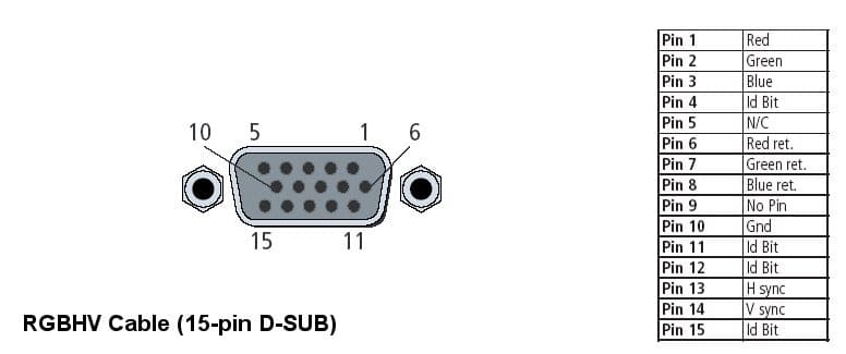
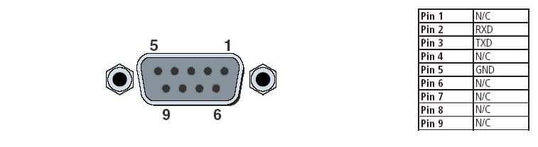
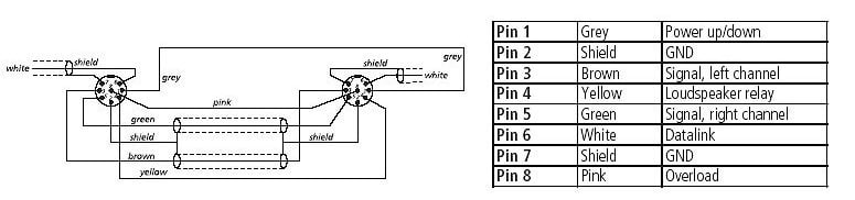
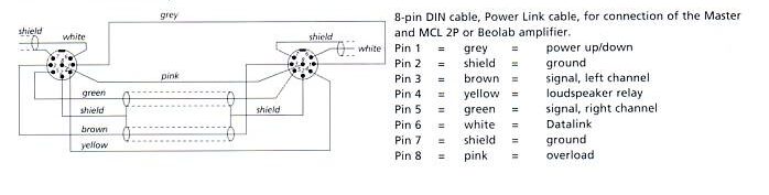
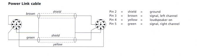
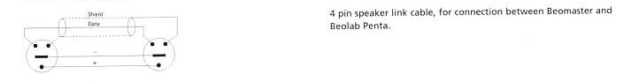
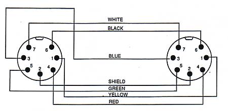
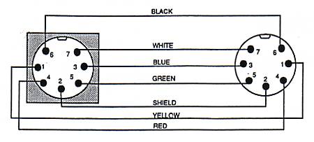
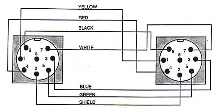
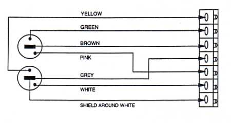
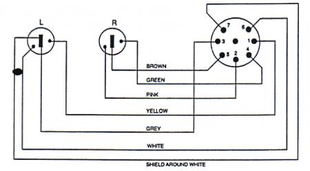
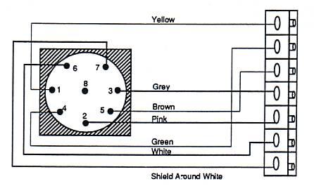
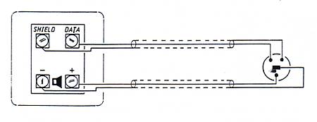
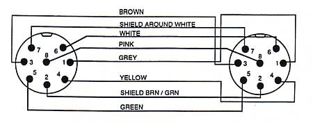
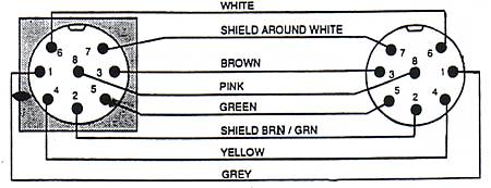
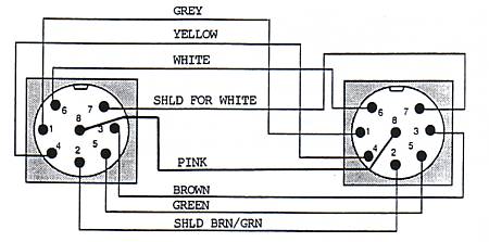
Connections
All necessary connection facilities were incorporated in Beomaster 6000: 4-channel record player, 2 or 4-channel tape-recorder. 4-channel headphones or two sets stereo headphones.
Beomaster 6000 was perfectly matched to partner the Beocord 5000 cassette recorder (introduced 1975). Beomaster 6000 was featured in an exhibition at New York’s MoMA (Museum of Modern Art) in 1975. At the time of its release it was the flagship of Bang & Olufsen’s hi-fi product range and was quite expensive to purchase. The UK price in 1978 was £581.50.
Accessories:
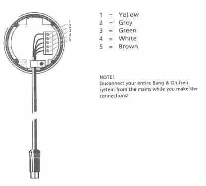
FM room aerial
An FM aerial type 8902010, was designed for use with Beomaster 6000 to be used in the home, within a certain radius of the radio transmitter. It was easily positioned at the rear of Beomaster 6000 and its two telescopic elements could be extended.