BeoLab 1
After purchasing a pair of brand new Beolab 1 I was dissatisfied with the sound (as I expressed in the BeoWorld Forum). Bang & Olufsen seemed to be unhelpful and a little arrogant in the matter, as to helping me resolve the issue.
In my opinion these big “pillar” speakers sounded razor sharp, ice-cold and screamy when playing CDs of good dynamic qualities.
As a technician I refused to accept this. I started researching everything I could about these speakers.
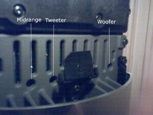
After having spent some time researching, I discovered three potentiometers on the active X–over located behind the covers (at the bottom), which controls each of the amplifier units with 3-4 Db. I started experimenting with these.
I quickly discovered that, when turning a potentiometer left, an element played less, and when turned right it played louder. I wrote down all the original values and continued experimenting.
After a little while I was able to localise each screw and what element it symbolised:
I have now customised the values on the screws and the result: a little more bass and less ice-cold and screamy sound from the mid-range element!
These customised changes have allowed me now to enjoy a little more listening, instead of getting worn out by the continuous metallic, cold, surgical and artificial sharp sound (especially at high volumes 50-56).
Warning: Before attempting any form of modifications, please be aware that modifications carried out by none B&O personnel could result in loss of warranty (as posted by our moderator). Further more, if you make the modifications be sure to “mark” the positions of the “damping bricks” as to where they are located in the cabinet. The following modifications are based on previous modifications made to my BeoLab 1s (where I changed all three potentiometer values).
Modifications carried out with the following setup: BeoSound 3000 and BeoLab 2.
Even with my previous modifications (to the potentiometers) I was never 100% satisfied with the outcome. Though the modifications (in my opinion) were a great improvement, I decided to see if any other modifications could be carried out (as to improve the sound).
So, in my quest for perfection, I recently decided to disassemble my BeoLab 1s.
The first thing I noticed was that very little damping material had been used to damp the reflection of the inner-waves. As illustrated on the picture below, only four small “damping” bricks and one very thin sheet of damping material (at the bottom) are used.
As you can see on the picture, no damping material has been used on the upper part of the speakers (where the upper woofer is located), which seems very odd to me.
Now if you disassemble other speakers of high-end brands like B&W, Tannoy etc you would see that the speakers are filled with damping material. And even as insignificant that this may seem to many of you, I can assure you that it has a great impact on the “sound experience” from a speaker.
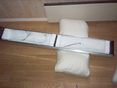
So I decided to modify the BeoLab1 with high-quality damping material, enough for 30 – 40 litres. And filled the whole cabinet with it (as illustrated on the bottom picture):
Before assembly, I moved the “bricks placement” to maximum width to see how the woofers sounded. When placed far apart, the woofers sounded softer (much more like the Pentas) and when placed close together (like originally mounted), it sounded punchier! So I decided to experiment with the placement of the “bricks”, and eventually found a satisfying position for them.
With the original placement of the “bricks” the woofers theoretically only had about 2-3 litres of volume.
These customised changes, have made my BeoLab 1s much smoother and I think I’m nearing pure perfection.
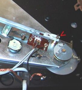 The problem is a small brass pin that is sticking. You will need to disassemble the BeoGram.
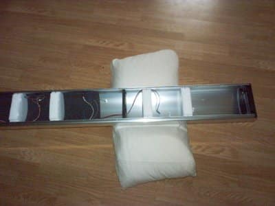