Aerial Impedance, VHF UHF 75 ohms may be altered to 240 ohms by removing transformer 0972085/0507745 240 ohms only Extension Speaker Connection 3-5 ohms Gramophone Connection Prepared for gramophone (Beogram 1000, Type 5202) and crystal pick-up Power Consumption (Measured with moving-iron instrument) TV: 1100 mA (Approx. 245 W) FM: 300 mA (Approx 70 W) GR: 250 mA (Approx 55 W) Power supply 220 V, DC or AC Power Output 2.5 W Tape Recorder Connection Prepared for diode output Tuning FM tuner, 87.5 – 100.5 Mc/1: with AFC VHF tuner with mechanical memory device: channels 2-11 UHF tuner with continuous tuning: channels 21-70 470-870 Mc/s Valves PPC 189, VHF RF amplifier PCF 86, VHF mixer
3 x EF 184, Video IF amplifiers PCL 84, AGC and video output stage A59 – 11W, Picture tube, 23 in. 114º UCF 80 1, Noise inverter and 1st sound IF amplifier UCF 80 2, AGC diode and 2nd sound IF amplifier UCL 82, AF amplifier and output stage PCF 80 3, Separator PCL 85, Video output stage ECC 81, Automatic line control PCF 80 4, Line oscillator PL 500, Line output PY 88, Booster diode DY 87, High voltage diode UCC 85, FM RF amplifier and mixer UCH 81, 2nd FM mixer UM 84, Tuning indicator Dimensions W x H x D, Beovision 1500 K: 60 x 49.3 x 39.6 cm Dimensions W x H x D, Beovision 1500 SJ: 63.6 x 84.7 x 42.9 cm Weight, Beovision 1500 K 28.5 kg Weight, Beovision 1500 SJ 36 kg
Gold or Silver membership required to view documents
Available documents are listed, if none are listed then please reach out to see if we have them.
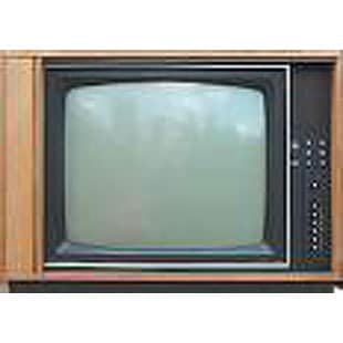
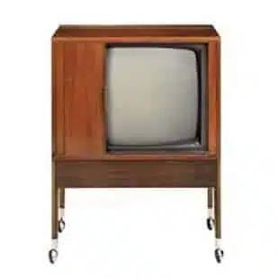
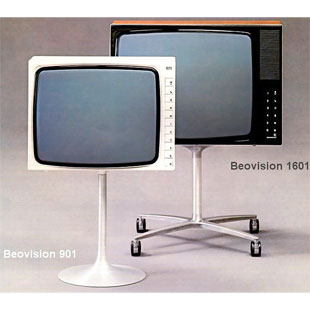
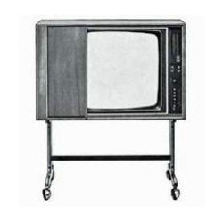
The Beovision 1600 replaced the Beovision 1400 range and included a new all-transistor chassis. As before, a 24” wide-angle tube was fitted, the largest monochrome tube that was available at the time. In contrast to the 1400 range, only one cabinet style was available, a table model, though this could be fitted with an optional pillar stand for free-standing use. The design was simple and elegant, with the minimum of cabinet work around the screen.
The controls were all of a new design, and concealed when not in use. Each one was mounted in a small latching drawer marked with a graphical symbol to represent its function. To adjust a setting (volume, brightness etc), one only had to touch the relevant drawer lightly and it would open, allowing access to an edgewise rotary control. The tuning worked in a similar manner, where the tuning controls were hidden inside the channel selector buttons. To adjust the tuning, one would press the button one wished to adjust, thus selecting the channel, then press again to slide out the drawer to reveal the tuning scale and control.
To make the most of the instant picture possibilities that the adoption of transistors (instead of the valves in previous models) offered, the heater of the picture tube of the Beovision 1600 was left energised at all times. In order to extend the life of the tube, when the set was switched “off”, the heater was run at a slightly lower level of power. Even despite this, the picture appeared truly instantly as soon as the “on” button was pressed, something that no other range of Beovision TV sets has been capable of since.
The rest of the design was quite conventional, with the exception of the voltage regulator which could tolerate a very wide range of mains voltages without picture disturbance.
The Beovision 1600 was the last large-screen monochrome Beovision model
Picture tube: 61cm (4:3) Vertical and horizontal hold: automatic Flyback: blanked for vertical and horizontal deflection Tuning: 6-button diode tuning
Power output: 5 W Distortion: < 1% at 4W/1000 Hz Speaker: 800 ohms oval type, forward-facing Tone controls: continuously variable bass and treble Sound Intermediate Frequency Sound IF amplifier & detector employing integrated circuits Single-tuned filter and 4.43 MHz < filter Quadrature circuit
Dimensions W x H x D: 62 x 43.6 x 39cm Weight: 24 kg Mains voltage: 190 – 265 V without switching Frequency: 50 – 60 Hz Power consumption: 100 W Connections: Inputs UHF aerial: 75 ohms Outputs Tape recorder output requires installation of a type 8903044 tape recorder kit
Gold or Silver membership required to view documents
Available documents are listed, if none are listed then please reach out to see if we have them.
Henning Dahl-Mikkelsen – ‘Mik’ – designed Bang & Olufsen’s well-known logo in 1931. But Dahl-Mikkelsen created also other well-known figures than Bang & Olufsen’s logo. He is also the man behind the comic strip Ferd’nand, a world-wide success and published in 15-16 different countries. In 1999 it was 60 years since Dahl-Mikkelsen began developing Ferd’nand. Since 1939 Ferd’nand has been published in 100 to 120 papers all over the world. Until his death in 1982 Dahl-Mikkelsen made more than 15,832 Ferd’nand strips.
Fact – The very first product to bear the ‘new’ Bang & Olufsen logo was the tone-arm and magnetic cartridge of 1933.
Henning Dahl-Mikkelsen was born in 1915. After grammar school he spent two years as a painter’s apprentice with a part-time job as an advertising artist. In 1931 he contacted Bang & Olufsen and showed them a logo he wanted to sell. The logo was very typical of the period and in the style known as Bauhaus. Dahl-Mikkelsen wanted five Danish kroner for the drawing, but Svend Olufsen, who was otherwise known for being careful with his money, offered Dahl-Mikkelsen ten kroner – twice Mik’s asking price! Bang & Olufsen has being using the logo since 1931, when it was registered.
Dahl-Mikkelsen then moved to Copenhagen and found employment in an animation studio. That led to a job in London in 1935, where he was senior artist for an English film company. His great example was Walt Disney’s Mickey Mouse cartoon and for a number of years he worked with cartoon films until on 3 May 1937 he began the comic strip Ferd’nand. That same year he created the pantomime comic strip Ferd’nand for the Danish Press Agency PIB Copenhagen Copenhagen. It had its debut in two English newspapers and in May also began appearing in Danish provincial newspapers. Only after the New York Herald Tribune and the Chicago Tribune had bought publication rights to the series did the major Danish daily newspapers show interest. After the Second World War the strip achieved international success, especially with the Americans. Mik, as Dahl-Mikkelsen now called himself, emigrated to the USA to be closer to his most enthusiastic readers.
Success
Ferd’nand was a success in Denmark even under the German occupation of the country from 1940-45. The success set Mik to work on still another series, the double strip Familien Hansen (The Hansen Family). The comic book version of Jens Locher’s popular radio show about a typical Danish family’s humorous everyday experiences was published in the magazine Landet (The Country) from 1942-48, with Mik as the artist until 1946. He was succeeded by Chris, Helge Hau and then Holger Philipsen.
Mik had created his first comic for The Country as early as 1941, with De gamle guder (The Old Gods) first appearing in issue no. 35. This full colour page with charming caricatures took as its starting point the Nordic mythology and life of the gods in Valhalla in a story by Harald H. Lund. The series was published as a comic book in 1943 by Illustrationsforlaget (Carlsen) under the title Thor og hans hammer (Thor and his Hammer).
Mik’s third comic in Landet was the children’s series Lise og Lasse. It started as a double strip in colour in 1944 and was written by Harald H. Lund. It was an imaginative epic series from fairy tale- and toyland in a style reminiscent of Harry Nielsen’s Bamse og Dukke Lise (Teddy Bear and Lise the Doll), transformed into detailed drawings rich in perspective. When Mik left Denmark in 1946 to try his luck in the USA, Lise and Lasse was continued by Ib Steinaa until 1950, however with little success.
Later years
Mikkelsen moved to California and continued to draw the strip until his death in 1982. Today, Ferd’nand continues to be drawn in “Mik’s” style by Henrik Rehr. Rehr says he was honoured when asked to draw Mikkelsen’s character. “I grew up with Ferd’nand and have always admired the strip. It’s one of the classic silent strips and I liked the international appeal of working without words.”
Ferd’nand is the classic “silent” comic strip, starring a wide-eyed cherubic mime, his wife, son and dog. Every day is a new adventure for the title character as he confronts life and fate with wonderful expressiveness. From circus performer to bank cashier to orchestra conductor, Ferd’nand has spent almost six decades as the pantomiming protagonist of middle class life. A timeless classic with universal appeal, Ferd’nand is one of the 10 longest-running comic strips still being drawn.