Posted on

Dolby HX-Pro

Dolby HX-Pro

Dolby HX-Pro

When tape recording was in its infancy, the signal to be recorded was fed directly to the recording amplifiers and then on to tape. But it was soon discovered that distortion could be reduced by adding a ‘bias’ to the signal – at first in the form of a DC signal added to the signal to be recorded and then later a high frequency AC signal. The frequency of the bias signal is always substantially higher than the highest frequency to be recorded and thus does not interfere with the audible signal.

It was also found that the level of the bias signal is critical to the recording of high frequencies and therefore to the frequency response of the recording. Traditionally, the bias signal level was set at the factory before the tape deck is shipped and remained fixed in use. The level chosen is a compromise for different kinds of music in the judgement of the manufacturer and is different for each brand; and often different for each model within a single brand. The optimum bias level had been the subject of debate between experts for a long time.

Dolby HX-Pro

Engineers at Dolby Laboratories suspected that the high frequency content of the music itself had an influence on the frequency response of the recording and launched a system called HX (headroom extension). This was a complex feed forward system that measured the frequency content of the music, calculated the bias required and added this level of bias to the input signal. While the system functioned better than a fixed bias system, it was not the optimal solution.

Jørgen Selmer Jensen of Bang & Olufsen also had his suspicions about the nature of the bias and its influence on frequency response. But he took a different approach to correcting the problem and in the process got a bonus in performance. He deduced that the high frequencies of the music being recorded were in fact acting as additional bias for the music itself and thus degrading performance. Experimenting with various kinds of music, he devised an algorithm for the bias equivalent added by the high frequency content of the input signal. It was then a relatively simple matter to construct a feedback system that reduced the bias by precisely this amount, on a real time basis. This had the effect of making the frequency response of the recorder linear, once the static bias had been set in the factory, irrespective of the kind of music being recorded.

The system was found to give an added bonus in use. The undistorted signal level that can be recorded on tape is also dependant on the level of the bias mixed with the audio signal, and was also a part of the factory setting compromise. With HX-Pro it was found that a very much higher level could be recorded, with low levels of distortion. In fact even when the tape was overloaded, the rise in distortion was small compared to recorders with a fixed bias level.

This system was launched with a license to Dolby Laboratories, who would market the system as Dolby HX-Pro, and has been used for many years not only in cassette recorders, but also in the professional recorder field.

Posted on

Masterlink

Masterlink

Masterlink

BeoLab 3500

BeoLab 3500 is an integrated link room speaker consisting of an active speaker with Master Link (ML) connection, an IR receiver and a display. BeoLab 3500 also has Master Control Link (MCL) connection. Furthermore, BeoLab 3500 has a built-in clock. BeoLab 3500 is supplied with a mains lead, a Master Link cable and a bracket for wall mounting.

Application: BeoLab 3500 is used in link rooms where you wish to have an integrated active speaker. From BeoLab 3500 it’s possible to listen to all sources from the main room, both audio and video sources. BeoLab 3500 has built-in sound control, meaning that tone and volume can be adjusted independently of the main room. With the tone control it is possible to adjust balance, bass, treble and loudness individually.

BeoLab 3500 offers the following local operation features:

Timer on/off

PLAY / ST.BY

Masterlink

Beolink® Active

Beolink® Active consists of a control box, an IR receiver, a receiver cable and a mains lead. Application Beolink® Active speakers are used in link rooms where active speaker are required. All Bang & Olufsen active speaker may be connected. Beolink® Active has built-in sound control, meaning that tone and volume can be adjusted independently of the main room.

With the tone control it is possible to adjust balance, bass, treble and loudness individually. With a Beolink® Active it is possible to distribute the sound from all main room products – both the video and audio sources.

Beolink® Active offers the following local operation features:

Timer on/off

PLAY / ST.BY

Volume up and down

Beolink® Video

Beolink® Video consists of a control box, a mains lead and a Datalink cable. Apart from this you need an coaxial cable from the HF outlet of the video tape recorder in the main room. This cable is connected to the aerial input of the link room TV.

Application: Beolink® Video is used in link rooms where both sound and picture are required via a Bang & Olufsen TV set. Beolink® Video is connected to the link room TV set by means of the Datalink cable.

With Beolink® Video it is possible to use all the sources in the main room. In particular it is possible to operate SAT and V.TAPE but it is further possible to watch a decoded programme from the TV set in the main room. In addition, it is possible to operate all audio sources, thereby using the speakers in Bang & Olufsen’s TV sets for obtaining audio sound. If you want even greater sound in the room you can connect Bang & Olufsen’s active speaker to the TV set.

Beolink® Video is connected to the TV set by means of the 7-pin Datalink cable and to the main room with a Master Link cable

Beolink® Converter

Beolink® Converter consisted of a control box and a mains lead.

Application: Beolink® Converter was used when audio and video products with Master Link and Audio Aux Link (Datalink) had to be interconnected. Beolink® Converter could be used in conjunction with both a video and an audio master. Beolink® Converter featured auto configuration, meaning that it was able to detect automatically whether it was installed in a Master Link audio or in a Master Link video system. Configuration took place when it was connected to the mains.

Beolink® Converter was used in compatibility setups.

AV9000 Audio Kit

The Beosystem AV 9000 Audio Kit consisted of a control box and a mains lead.

Application: the AV 9000 Audio Kit is used to obtain compatibility between Beosystem AV 9000 and products without Master Link connection. AV 9000 Audio Kit was updated with a built-in power supply when it then featured auto configuration. The AV 9000 Audio Kit can be used in conjunction with Beovision AV 9000 only.

Note that the AV 9000 Audio Kit with switch cannot be used with the new 9-pin Master Link cable

ML/MCL Converter

ML/MCL Converter consisted of a control box and an amplifier.

Application: ML/MCL Converter was used where a conversion from Master Link (ML) to Master Control Link (MCL) was wanted. Such a conversion was required if you wanted to maintain the existing Master Control Link system although the audio system in the main room was replaced with a Master Link driver; for example a BeoSound Ouverture. ML/MCL Converter could also be used in conjunction with a Beosystem AV 9000 with an AV 9000 Master Panel.

Posted on

Datalink

Datalink

Datalink

Getting the message through

Datalink was the first digital language developed by Bang & Olufsen and allowed various components of a music system to work in conjunction with each other. It used the addition of two extra pins to a standard 5-pin DIN plug via which a digital code was sent. It was a way whereby products could ‘talk to each other’. Datalink is the forerunner of Beolink®.

Datalink

The DIN connector has two pins for control signals, one pin as an audio ‘common’, two pins for stereo ‘in’ and two more pins for stereo ‘out’. The control pins are referred to as Datalink pins and these carry signals to do the following:

* transfer program-location data to the primary component to show up on the primary unit’s console, two-way remote controls, display-equipped BeoLab speakers or Beovision TVs that are installed in other rooms and part of their Beolink ‘multi-room’ audio-video infrastructure

* ‘open up’ the audio inputs on the Beomaster or BeoCenter if the local ‘PLAY’ key is pressed on the unit

* accept control signals to control the device from either the primary unit or a remote control

The original idea was seen in a prototype system called Beosystem 6000 which comprised a stereo receiver, stereo tangential tracking turntable and an advanced auto reverse reel to reel tape recorder. This system was never put into production but styling cues from the Beomaster led to the Beomaster 6000 quad receiver, the record player became the Beogram 4000 but the Beocord was dropped after only 6 examples were made. The idea of each component being able to talk to each other was postulated but no system was put into production based on this design.

The first production model with any type of link system was the Beomaster 2400 which, when connected to a Beogram 4004, allowed remote control of the Beogram via an ultrasonic remote control. Unlike previous systems, all the major controls on the Beogram and the Beomaster were electronic and hence suitable for remote operation. The system was later to include a radial Beogram as well, the Beogram 2402. This system however was a one off and was incompatible with later versions of Datalink. The Beogram and receiver were connected via a captive 7-pin lead on the Beogram.

Datalink first was seen in its full glory in the BeoLab 8000 system in 1981. Unlike the earlier system, full remote control of all the different sources was now possible, with play, record, cueing, programme selection and volume control all possible at the press of a single button on an infra red remote control. The system also allowed one to press a start button on any of the sources which would switch on the Beomaster or vice versa. All the sources were attached to the Beomaster by 7-pin DIN leads. An important point was that the Beomaster remained the hub of the system with all commands from the remote control travelling via the infra red receiver on the Beomaster and Datalink being the messenger to the source.

The system was refined over the years and eventually allowed all functions to be controlled remotely as seen in the Beosystem 7000. These days, the system has fallen into disuse but the language continues in a different guise as MasterLink. No longer speaking between components in a single audio system, MasterLink connects systems together. Older systems can still communicate with the aid of the 1611 converter which translates Datalink to the newer codes.

Products with Datalink:

BeoMaster

  • 2000**
  • 4500
  • 7000
  • 2400 / 2400-2
  • 5000
  • 8000
  • 3000
  • 5500
  • 3300
  • 6000
  • 3500
  • 6500

BeoCord

  • 2000
  • 5000
  • 6500***
  • 8004
  • 3300
  • 5500 ***
  • 7000 ***
  • 9000
  • 3500
  • 6000
  • 8000
  • 4500
  • 6002
  • 8002

BeoCord VCR

  • VHS 91
  • VHS 91.2

BeoGram

  • 1900/1902
  • 4500
  • 6002*
  • 9000
  • 2000
  • 5000
  • 6006
  • 9500
  • 3000
  • 5005
  • 6500
  • 3300
  • 5500
  • 7000
  • 3500
  • 6000*
  • 8000
  • 4002
  • 6000
  • 8002

BeoGram CD

  • 3300
  • 5500
  • 3500
  • 6500
  • 4500
  • 7000
  • CD50

BeoCenter

  • 2300
  • 9000
  • 2500
  • 9300
  • 8000
  • 9500
  • 8500

BeoSound

  • 4000/Ouverture

Notes:

* Datalink communication in the Beogram 6000/6002 is one-way, which means that pressing /PLAY/ on Beogram 6000/6002 will not start the Beomaster/Beocenter

** Beomaster 2000 cannot be operated by remote control

*** Beocord 5500/6500/7000 have some special functions, for example tape counter and adjustment of recording level via remote control, which can be only operated with Beomaster 5500 and MCP5500

Posted on

Struer – a Town in the Making

Struer - a Town in the Making

Struer – a Town in the Making

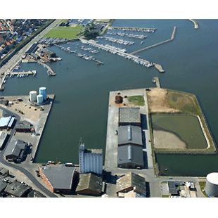
Struer is a market town by Limfjorden in the western part of Jutland. Struer is one of the youngest towns in Denmark (founded 1917) and currently has around 19 000 inhabitants. A Danish newspaper once named it the ‘stockbroker belt’ of western Jutland.

Its marina is the largest in Limfjorden with its industrial harbour (from 1856) being the second largest after Aalborg. The city is well known because of the Bang & Olufsen’s predominance in the town.

Struer - a Town in the Making

The city of Struer owes its growth to the railroad, which arrived in 1865 with Jutland’s first railroad line from Århus/Randers over Viborg to Skive and Struer. Before its arrival Struer was a little town, that primarily functioned as a harbour for the residents of Holstebro; but after its arrival the town grew explosively into a big city, and eventually became one of Denmark’s most important railway connection points. Although the station has been expanded several times, the central part of the well-maintained building is one of Denmark’s oldest stations.

Fact – Struer received privileged status as a merchant town in 1917.

Until the end of the 1960s Struer Station served as the headquarters for the central West Jutland administration of DSB, Danske Statsbaner (“Danish State Railways”). More than 300 DSB employees still work in Struer today.

Fact – Bang & Olufsen, Denmark’s only radio/TV manufacturer today, is the city’s most important business, and they employ almost a third of the town’s population.

Posted on

Bang & Olufsen – Museum in Struer

Bang & Olufsen - Museum in Struer

Bang & Olufsen – Museum in Struer

From miniature plans to full-scale development

Bang & Olufsen Museum at Struer, Denmark

The year 2003 saw the continuation of an exciting project launched the previous year, to design and construct a museum dedicated to the technological skills of the company’s workers and its audio-video products which have now been in production in the town for over three-quarters of a century.

The new Bang & Olufsen Museum will be constructed in the centre of the town of Struer – a town synonymous with the company’s history – on Søndergade, at the side of the town’s existing museum.

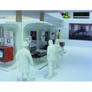
Pictured – A glimpse into the proposed Bang & Olufsen Museum in Struer, where Jørgen Michaelsen already has placed the first ‘visitors’. The models here depict the company’s products throughout the years. Note the photograph on the rear ‘wall’ showing employees on the steps of the old building at Quistrup

” B&O Museum ready in miniature. Negotiations about Bang-Foundation’s gift to Struer municipality begin today, Tuesday.

Bang & Olufsen - Museum in Struer

When plans of the gift were revealed in April they were in the form of architect Freddy Nielsen’s drawings, but since then, the former B&O employee, architect Jørgen Michaelsen Venø, has created a miniature of the Project adding to it the latest expansion schemes. It turned out to be necessary to get more room for the museum’s workshops; expanding the lowest levels by a couple of hundred square metres has solved the problem.

The museum will be underground, only a metre of the top level and the glass roof will be visible on the lawn between the Struer Museum and Buchholtz’s house in Søndergade. The museum will be on three levels with underground connections to existing museum buildings.

The project will cost an estimated 10 million DDK, but the Board of the Kirsten and Peter Bang Foundation is willing to pay. The Board consists of Kirsten and Peter Bang’s four children, Jens, Lotte, Peter and Dorte, and they gathered on Friday to approve the expansion of the project. It is now up to the Struer municipality to play its part of the project in these times of savings. It will have to buy half of the property at Søndergade 21. The house must be demolished to make room for the museum, but the municipality already owns the other half of the property.

The municipality will also have to pay for the part of the museum that will be placed under the northern wing of Struer Museum, where the connection to the B&O Museum will be. In addition to this they will also pay for the necessary facilities in the museum and its daily operation.

There is no doubt that a B&O museum of this standard will generate profit by virtue of increased tourism – it is not everyday that the municipality is offered a gift worth 10 million DDK, thereby recouping the municipality’s original outlay.

Architect Jørgen Michaelsen was a former leader of Bang & Olufsen’s Shop Design department. Before retirement he was involved in exhibition model-making. This talent has been utilised more recently for the proposed Bang & Olufsen Museum in Struer. Shown here, Michaelson presents the result of his efforts to Lars Peter Bang, who manages the Museum Project on behalf of the Bang-foundation.

Posted on

Bang & Olufsen Repair – Multicare Electronics

Bang & Olufsen Repair – Multicare Electronics

Bang & Olufsen Classic Service Centre


Being part of the Bang & Olufsen Classic Service Alliance, our ambition is to give new life to cherished classics. We as a Classic Service Centre have a service team of dedicated, technical specialists that are among the best and most experienced within our field. Building on a network of knowledge and expertise, we provide services to any of your classic Bang & Olufsen products, ranging from repair and restoration to system integration and individual custom solutions.

Multicare Electronics Ltd

Handing in a cherished product, which may have played an important part of your life for many years, means trust, hope and expectation of a carefully selected specialist. Please be assured that we are as passionate about your beloved classic Bang & Olufsen product as you are, and we will do our utmost for it to remain a valued part of your home. Please do not hesitate to contact us for an evaluation of the services and solutions we are able to offer for your product or complete setup.

We dedicate our work to bringing new life to your cherished classic products. Our team of experienced service specialists provides product repair and restoration for products outside the regular service period, integration between legacy and new systems as well as custom solutions such as upgrade to newer technologies. Over the years, we have built a stock of spare parts for legacy products, and in close collaboration with Bang & Olufsen, we are able to source certain scarce parts even today. Our extensive expertise also allows us to develop hand-crafted, alternative repair solutions to keep your beloved classic Bang & Olufsen products alive.

Posted on

Bang & Olufsen – Struer Headquarters

Bang & Olufsen's headquarters in Struer

Multicare

Creating a dialogue between technology & Nature

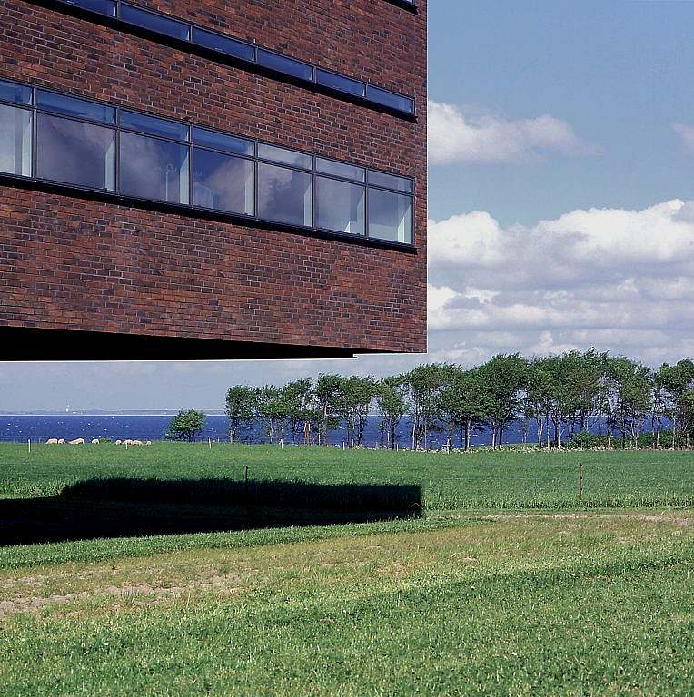
The new Bang & Olufsen Headquarters in Struer, Denmark are affectionately known as ‘The Farm’ and were designed by Jan Sondergaard MAA of KHR Architects in 1997. It opened for business the year later. The building covers a total area of 1121 square metres and provides a working area of 5131 square metres.

‘The Farm’ is one of the most distinctive and talked-about Danish buildings with hybrid ventilation. The building is ventilated with the help of natural airflow when possible, and supplemented mechanically with helping fans when the natural pressure from wind and convection isn’t enough.

The building has three floors with a collective height of 12 meters. The floors are fitted with a large open office and a number of directors’ offices in addition to washrooms, elevators and the like. The north façade is outfitted in clear glass. The idea behind the construction is high quality with a minimum of technical mechanisms, which to the highest degree possible are hidden.

Bang & Olufsen's headquarters in Struer

The building is ventilated according to the principle of displacement, where lighter, cool air is brought into the lowest parts, and pushes heat and pollution upwards, where the air is sucked out or expelled into the attic. The air exits the building via two vents through the large axial fans. The fans remain stationary when the natural air pressure is sufficient, and at other times are regulated by the air quality in the building in the form of CO2 concentration. During the night, the fans can also be used for night cooling in periods of warm weather, by which the building’s solid parts are used to accumulate warmth during the daylight hours and radiate it back during the night. By this means the temperature during the day is reduced during the hot summertime, and one avoids using mechanical cooling.

Aalborg University has been involved in a number of target programs at the B&O building. The building has also been a “participant” in many Danish energy research studies and a number of international research projects.

The design of ‘The Farm’ was inspired by the solitary farmhouses typical of the area. The new main building and its courtyard form a sheltered space with an unfettered view of all activities. Like its historic models, the building makes an effort to create a dialogue between the function and technology of manmade structures and the poetic dimension of the surrounding landscape.

KHR and Jan Sondergaard have recieved many awards and accolades including First Prize in the Architechture for Humanity competition, beating entries from around the world

Posted on

Bang & Olufsen – Eastern European Plant – Koprivnice

Bang & Olufsen Koprivnice

Multicare

On 4 May 2006, Bang & Olufsen officially opened its first production facility outside of Denmark. The new factory is in Koprivnice, which is in the eastern part of Czech Republic close to Ostrava. Bang & Olufsen has invested eight million euros in the new 14,000 square metre factory and 130 employees are already working in the factory. The factory is geared for 200 employees and this target will be reached by summer 2007.

Bang & Olufsen Koprivnice

“This new factory placed right in the heart of Europe represents an important investment in the future of Bang & Olufsen,” explained Jørgen Worning, Chairman of the Board for Bang & Olufsen, in his speech for the official opening. “I am very proud to see the positive financial development Bang & Olufsen has shown over the last couple of years. The company is now geared for growth and it is our goal to have a turnover of about 800 million euros by 2010. It is an ambitious target and our new factory in Koprivnice will play an important part in this effort.”

Bang & Olufsen started discussing the idea of a new factory outside of Denmark back in 2003 and a dedicated team then investigated no less than 42 possible sites. Koprivnice was the final choice, and already by February 2006 production had started in the new facility. The factory is already handling several preassembly tasks and will also assemble products from the range of Bang & Olufsen music systems, loudspeakers and telephones.

“Bang & Olufsen’s attitude to technology is that it should work for our customers. At our headquarters and factories in Struer, in the west of Denmark, Bang & Olufsen has for 80 years manufactured some of the finest crafted products in the world. Now we have added this new factory to our product development and manufacturing facilities. We want to ensure that the quality of our products remains unmatched, and it is with great pride that we welcome Koprivinice to the Bang & Olufsen family” said Jørgen Worning during the official opening.

Posted on

Bang & Olufsen – Anodising

Bang & Olufsen Anodising

Multicare

Adding beauty and durability

Bang & Olufsen over the years, has become famous for not only its stylish products but for their ‘feel’ and looks. Many products produced nowadays are of a hard-wearing aluminium; aluminium which has gone through the process of anodisation in order to harden the aluminium surface considerably and make it highly resistant to physical damage such as scratching. As the products’ mirror finish and smooth surface without protrusions are easily cleaned, their beautiful appearance will be the same for many years.

Bang & Olufsen Anodising

Anodised aluminium has been a Bang & Olufsen hallmark for many years, but as the mirror-finished anodisation process is one of the most demanding metallurgic surface processes, Bang & Olufsen is the only manufacturer of audio and video equipment to use it. Anodising aluminium successfully combines science with nature in order to create one of nature’s best metal finishes.

The process is electrochemical which thickens and toughens the naturally-occurring protective oxide. The resulting finish, depending on the process, is the second hardest substance known to man, second only to diamond. The anodic coating is part of the metal, but has a porous structure which allows secondary infusions, (i.e. organic and inorganic colouring, lubricity aids, etc.).

Anodising Definitions and Methods

While the chemical anodising process remains the same for all applications, the mechanical methods vary according to the two physical types and shapes of metals used.

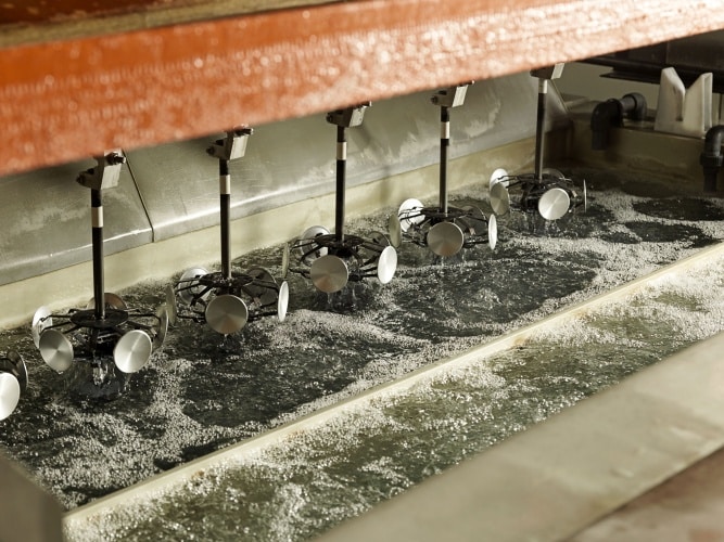
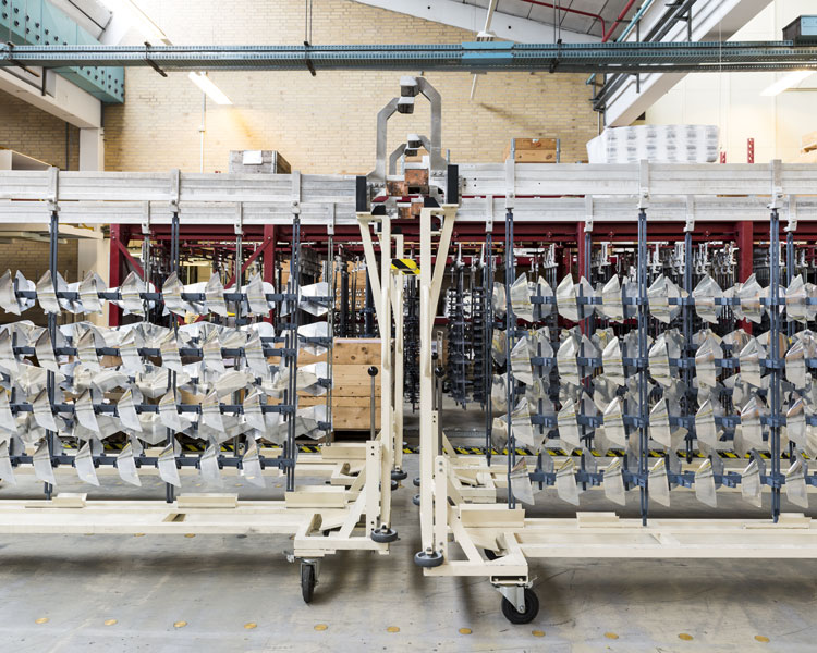
Batch Anodising involves racking parts and immersing them in a series of treatment tanks. In wider industry, extrusions, sheets or bent metal parts, castings, cookware, cosmetic cases, flashlight bodies and machined aluminium parts are just a few of the items that are batch anodised.

Appearance options and quality are improved through the use of dyes and special pre-treatment procedures. This makes the aluminium look like pewter, stainless steel, copper, brushed bronze or polished brass and can also be coloured with brilliant blues, greens, reds and many varieties of metallic gold and silver (see, for example, the range of BeoLab 4000 finishes). The unique dielectric properties of an anodised finish offer many opportunities for electrical applications.

The surface of the aluminium itself is toughened and hardened to a degree unmatched by any other process or material. The coating is 30 percent thicker than the metal it replaces, since the volume of oxide produced is greater than that of the metal replaced. The resulting anodic coating is porous, allowing relatively easy colouring and sealing.

Hard Anodising is a term used to describe the production of anodic coatings with film hardness or abrasion as their primary characteristic. They are usually thick by normal anodising standards (greater than 25 microns) and they are produced using special anodising conditions (very low temperature, high current density, special electrolytes). They find application in the engineering industry for components which require a very wear resistant surface such as piston, cylinders and hydraulic gear. They are often left unsealed, but may be impregnated with materials such as waxes or silicone fluids to give particular surface properties.

Anodising is accomplished in five carefully controlled, calibrated, quality-tested stages:

Cleaning:

  • Alkaline and/or acid cleaners remove grease, and surface dirt

Pre-treatment:

  • Etching. An appealing matt surface finish is created with hot solutions of sodium hydroxide to remove minor surface imperfections. A thin layer of aluminium is removed to create a matt or dull finish
  • Brightening. A near mirror finish is created with a concentrated mixture of phosphoric and nitric acids which chemically smoothes the aluminium’s surface

Anodising:

  • The anodic film is built and combined with the metal by passing an electrical current through an acid electrolyte bath in which the aluminium is immersed. The coating thickness and surface characteristics are tightly controlled to meet end product specifications

Colouring:

  • Colouring is achieved in one of four ways:
    • (i) Electrolyte Colouring – After anodising, the metal is immersed in a bath containing an inorganic metal salt. Current is applied which deposits the metal salt in the base of the pores. The resulting colour is dependent on the metal used and the processing conditions (the range of colours can be expanded by over-dyeing with organic dyes). Electrolytic colours can be specified from any AAA member. Commonly used metals include tin and cobalt. This process offers colour versatility and the most technically advanced colouring quality.
    • (ii) Integral Colouring – This so-called one-step process combines anodising and colouring to simultaneously form and colour the oxide cell wall in bronze and black shades while more abrasive resistant than conventional anodising. It is the most expensive process since it requires significantly more electrical power.
    • (iii) Organic Dyeing – The organic dyeing process produces a wide variety of colours. These dyes offer vibrant colours with intensities that cannot be matched by any other paint system on the market. They can also provide excellent weather-fastness and light-fastness. Many structures built with these finishes have lasted more than 20 years. The colour range can be broadened by over-dyeing the electrolytic colours with the organic dyes for a wider variety of colours and shades. This method is relatively inexpensive and involves the least amount of initial capital of any other colouring process.
    • (iv) Interference Colouring – An additional colouring procedure, recently in production, involves modification of the pore structure produced in sulphuric acid. Pore enlargement occurs at the base of the pore. Metal deposition at this location produces light-fast colours ranging from blue, green and yellow to red. The colours are caused by optical-interference effects rather than by light scattering as with the basic electrolytic colouring process. Further development will produce a greater variety of colours.

Sealing:

  • This process closes the pores in the anodic film, giving a surface resistant to scratching, abrasion, crazing and colour degradation.

Quality Control

  • Throughout the entire anodising process, the process and quality of the product is strictly monitored. The application of electrical power and colour is pre-programmed and verified on all batches and coils. This quality control ensures uniformity to end product specifications for film thickness, density, abrasion resistance, corrosion resistance, reflectivity, image clarity, insulation properties, adhesion and sealing.
  • The unique anodised finish is the only one in the metals’ industry that satisfies each of the factors that must be considered when selecting a high performance aluminium finish.

Features of anodised aluminium:

  • Durability – Most anodised products have an extremely long life span and offer significant economic advantages through maintenance and operating savings. Anodising is a reacted finish that is integrated with the underlying aluminium for total bonding and unmatched adhesion.
  • Colour Stability – Exterior anodic coatings provide good stability to ultraviolet rays, do not chip or peel and are easily repeatable.
  • Ease of Maintenance – Scars and wear from fabrication, handling, installation, frequent surface dirt cleaning and usage are virtually non-existent. Rinsing or mild soap and water cleaning usually will restore the anodised surface to its original appearance.
  • Aesthetics – Anodising offers a large increasing number of gloss and colour alternatives and minimises or eliminates colour variations. Unlike other finishes, anodising allows the aluminium to maintain its metallic appearance.
  • Cost – A lower initial finishing cost combines with lower maintenance costs for greater long-term value.
  • Health and Safety – Anodising is a safe process that is not harmful to human health. An anodised finish is chemically stable, will not decompose; is non-toxic; and is heat-resistant to the melting point of aluminium. Since the anodising process is a reinforcement of a naturally occurring oxide process, it is non-hazardous and produces no harmful or dangerous by-products.
  • Colour – Anodising provides depth and variety of colour with a brilliant metallic lustre.
  • Texture Choice – Anodising can provide a variety of textures from mechanically polished to heavily etched giving that extra dimension to a project.
Posted on

Bang & Olufsen – The Listening Panel

The Listening Panel

Multicare

Listening for perfection

While Bang & Olufsen uses the most advanced technology in the industry for measuring audio performance, the company never forgets that it isn’t the technology which has to enjoy the fruits of its labours, but its customers.

That is why at a time when measurements have become ever more sophisticated, Bang & Olufsen established in 1983 its Listening Panel equipped with that most sophisticated of all instruments – the human ear!

The Listening Panel

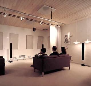
Every Tuesday afternoon, the company’s painstakingly-selected panel of seven people aged between 25 and 55, gather in a specially constructed listening room to evaluate the latest prototypes, early production models and products from rival manufacturers. Each member of the panel undergoes a special training course to determine the consistency of their evaluations. Band & Olufsen also arranges frequent trips to live concerts to establish ‘real music’ as a reference standard.

The listening panel is never told which piece of equipment it is being asked to evaluate. The speakers are hidden behind acoustically-transparent curtains to ensure that it is only the audio performance that influences the members’ judgement. That ensures that tests are always carried out objectively and are not swayed by any uncontrolled factors like brand loyalty, design looks or perceived price.